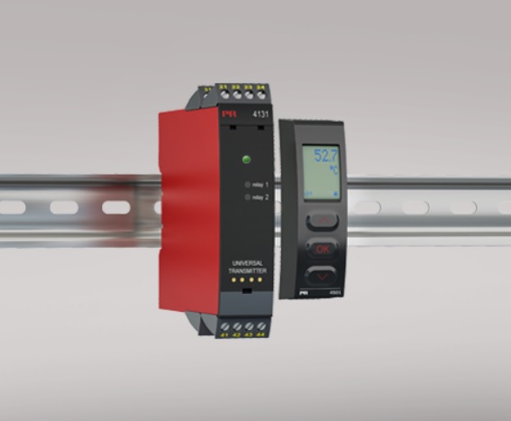
Universal trip amplifier
Input for RTD, TC, Ohm, potentiometer, mA and V
2 adjustable alarm limits
FM-approved for installation in Div. 2
2 relay outputs
Universal AC or DC supply
Advanced features
Programmable via detachable display front (4501), process calibration, relay simulation, password protection, error diagnostics and selection of help text in several languages.
Application
Process control with 2 pairs of potential-free relay contacts which can be configured to suit any application.
Trip amplifier with window function defined by a high and a low setpoint. The relay changes state outside the window.
Relay latch function, where the relay is activated and can only be reset manually.
Sophisticated sensor error surveillance, where one relay holds the state immediately prior to the sensor error, while allowing the process to continue.
The other relay can be set for sensor error alarm so that the defect sensor can be replaced immediately.
Technical characteristics
When 4131 is used with the 4501 display / programming front, all operational parameters can be modified to suit any application. As the 4131 is designed with electronic hardware switches, it is not necessary to open the device for setting of DIP-switches.
A green front LED indicates normal operation and malfunction. A yellow LED is ON for each active output relay.
Continuous check of vital stored data for safety reasons.
3-port 2.3 kVAC galvanic isolation.

